You’ve spent hours on that design. Every dimension is perfect. Every bend is exactly where you want it. You send the drawing to the fabricator, feeling confident.
Then the fabricator calls and says, “We can’t make this.”
Frustrating, right? I’ve been on the other end of that call more times than I can count. And here’s the thing—most of the time, the design is beautiful. It just doesn’t match the reality of how sheet metal bending actually works.
Let me walk you through what actually happens on the shop floor, why your bends sometimes can’t be made, and how to design for real-world sheet metal fabrication.
The Gap Between CAD and Reality
Here’s something CAD software doesn’t tell you: every bend needs room to happen.
Your screen doesn’t show the tool. It doesn’t show the machine. It doesn’t show the physical limitations of a press brake pushing metal into a die. But on the shop floor, those limitations are very real.
Why Bends Get Rejected
Let me explain the most common reasons I see designs that look perfect on screen but can’t be made on our machines.
1. Flanges That Are Too Short
Every bend needs a minimum flange length. The press brake pushes the material into a V-shaped die. If your flange is too short, the material won’t sit properly in the tool. The result? Inconsistent bends or crushed edges.
How to fix it: As a general rule, keep flanges at least four times the material thickness. For 1.5mm steel, that means a 6mm minimum flange. If you need shorter flanges, we can talk about special tooling—but that adds cost.
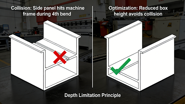
2. Boxes That Are Too Deep
Here’s a classic. You design a beautiful box with four tall sides. Looks great. But when we go to bend it, the second, third, and fourth bends crash into the machine.
The press brake has a maximum return flange height. Once you exceed it, the previously bent sides hit the machine frame before the next bend finishes.
How to fix it: Keep box heights reasonable relative to the distance between bends. If you need a deep box, consider welding separate sides or using a different fabrication method altogether.
3. Bends Too Close Together
When you have two bends close to each other, the first bend limits what you can do with the second. The tool needs room to access the second bend. If the first bend is in the way, you’re stuck.
How to fix it: Leave enough flat space between bends for the tool to fit. As a rule of thumb, keep the distance between bends at least five to six times the material thickness.
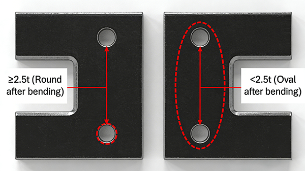
4. Features Too Close to Bend Lines
Holes, slots, cutouts, embosses—these all need to stay away from bend lines. When metal bends, the material stretches on the outside and compresses on the inside. Anything in that deformation zone will distort.
We covered this in another article, but it’s worth repeating: keep holes at least 2.5 times the material thickness away from any bend line.
How to fix it: Move features away from bend lines. If you can’t, plan to add them after bending.
5. Non-Standard Bend Radii
Here’s something that surprises a lot of engineers. Your drawing might call for a 2mm inside bend radius. But our standard tool might only produce a 1.5mm or 3mm radius.
Why? Because bend radius is determined by the V-die opening, not by magic. Changing the radius means changing the tool. And changing the tool takes time and money.
How to fix it: Ask your fabricator for their standard bend radius chart. Design to match their standard tooling whenever possible. Your parts will be faster and cheaper.
6. Flanges That Interfere With Each Other
You’ve designed a part with flanges on multiple sides. But when you bend the second flange, it hits the first one. When you bend the third, it hits both of them.
This is a common problem on complex parts. The order of bends matters. But sometimes, no matter what order you choose, the flanges just get in each other’s way.
How to fix it: Design with the bend sequence in mind. Talk to your fabricator about the best way to approach your part. Sometimes a small notch or split corner can solve the problem.
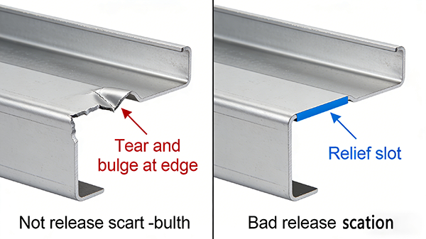
Standard Bend Reliefs and Why You Need Them
Here’s a simple sheet metal technique that solves a lot of problems: the bend relief.
When a bend runs all the way to the edge of a part, the edge can tear or bulge. A bend relief is a small cut that stops the bend before the edge, preventing damage and improving accuracy.
Standard rule: Make bend reliefs at least 1.5 times the material thickness wide, and longer than the bend radius. Add them to your drawing. Your fabricator will thank you.
How to Design Parts That Can Actually Be Made
Here’s my practical advice after twenty years of looking at drawings and making parts.
Talk to your fabricator early. Before you lock in your design, send it to us. We’ll tell you what works and what doesn’t. A five-minute conversation can save you weeks of rework.
Use standard tooling whenever possible. Standard tools are faster, cheaper, and more reliable. Ask for your fabricator’s standard bend radius, standard flange heights, and standard tolerances.
Think about the bend sequence. How will the machine reach each bend? Will previously bent flanges get in the way? If you can’t picture it, ask someone who does it every day.
Build a prototype. For complex parts, don’t go straight to production. Run a few prototypes. Bend them. Measure them. See what works. Adjust the design. Then run the full order.
Common Questions I Get From Designers
Q: Can I bend any material?
A: Almost any metal can be bent. But different materials behave differently. Soft aluminum bends easily. Hard stainless steel needs more force and has more springback. High-strength steels can crack on tight radii. Know your material before you design.
Q: How tight can my inside bend radius be?
A: As a rule of thumb, the minimum bend radius is about the same as the material thickness. For soft aluminum, you can go tighter. For hard stainless, you might need to go looser. When in doubt, ask your fabricator.
Q: Can I bend a part after welding?
A: Not usually. Welding changes the material properties around the weld zone. That area becomes harder and more brittle. It can crack when bent. Plan your sequence: bend first, then weld.
The Bottom Line
Good sheet metal fabrication starts with good design. But good design doesn’t happen in a vacuum. It happens when engineers and fabricators talk to each other.
The drawings that work best aren’t the ones with the tightest tolerances or the most clever features. They’re the ones designed with the actual machine, the actual tooling, and the actual material in mind.
Next time you’re designing a bent sheet metal part, ask yourself: how will this actually be made? If you’re not sure, give us a call. We’re happy to help.
Have a design you’re not sure about? Send us your drawing. We’ll review it and tell you what’s possible, what’s tricky, and how to make it work.